Chapter 4.1: Memory Access
Introduction
Learning Outcomes
Build valid memory operands from BX, SI, DI, BP and a displacement.
Compute the effective address, and the physical address from segment:offset.
State the access size with byte ptr / word ptr; read little-endian data.
Tell valid operand combinations apart and trace copy and swap programs.
Addressing Modes
Memory Access
- Memory is addressed through the BX, SI, DI and BP registers.
- Combining these registers (and a constant) inside
[ ]reaches different memory locations; these combinations are the addressing modes.
| Register(s) only | + d8 (8-bit displacement) | + d16 (16-bit displacement) |
|---|---|---|
| [BX + SI] | [BX + SI + d8] | [BX + SI + d16] |
| [BX + DI] | [BX + DI + d8] | [BX + DI + d16] |
| [BP + SI] | [BP + SI + d8] | [BP + SI + d16] |
| [BP + DI] | [BP + DI + d8] | [BP + DI + d16] |
| [SI] | [SI + d8] | [SI + d16] |
| [DI] | [DI + d8] | [DI + d16] |
| d16 (direct address) | [BP + d8] | [BP + d16] |
| [BX] | [BX + d8] | [BX + d16] |
These 24 combinations are all the memory choices of the mod/rm field in 8086 machine code. A bare [BP] is encoded by the assembler as [BP + 0] (d8 = 0).
Addressing Modes
The Combination Rule
- BX and BP never appear in the same mode.
- SI and DI never appear in the same mode.
- Modes with BP use the SS segment; modes without BP use DS.
[BX+5]→ base + d8 (DS)[BX+SI]→ base + index (DS)[DI+BX-4]→[BX+DI-4], order does not matter (DS)[BP+SI+300]→ base + index + d16 (SS)
Addressing Modes
Displacement
22, 55h, -1.300, 5517h, -259.- A displacement can be a number or the offset of a variable:
[BX + arr]. - The assembler folds several constants into one:
[BX + 2 + 3]→[BX + 5]. - It may be written inside or outside
[ ]; the machine code is the same:[BX+5]=5[BX]=[BX]+5. - It is signed, so it can be positive or negative:
[SI-1]. - The assembler picks the short form (d8) when the value is in −128…127, otherwise the long form (d16).
[BX+2] → EA = 0001h.Addressing Modes
Valid or Invalid?
| Valid | Mode |
|---|---|
[BX] | register indirect |
[1234h] | direct address |
[SI+10] | indexed |
[BP+DI-2] | based-indexed (SS) |
ES:[BX+SI] | segment override |
| Invalid | Why? |
|---|---|
[AX], [CX], [DX] | cannot address memory |
[BL], [BH] | an 8-bit register is not an address |
[BX+BP] | two base registers |
[SI+DI] | two index registers |
[SP], [BX*2] | not on the 8086 (80386+) |
The table generates every valid combination: base (BX/BP) + index (SI/DI) + displacement, each optional.
Addressing Modes
Kinds of Addressing Modes
| Mode | Example | Where is the operand? |
|---|---|---|
| Immediate | MOV AX, 5 | in the instruction (constant) |
| Register | MOV AX, BX | in a register |
| Direct | MOV AX, [1000h] | DS:1000h |
| Register indirect | MOV AX, [BX] | DS:BX |
| Based | MOV AX, [BP+4] | SS:BP+4 |
| Indexed | MOV AL, [SI+3] | DS:SI+3 |
| Based-indexed | MOV AL, [BX+DI] | DS:BX+DI |
| Based-indexed + displacement | MOV AL, [BX+SI+8] | DS:BX+SI+8 |
The first two never touch memory; the rest compute an effective address (EA). Physical address = segment × 10h + EA.
Addressing Modes
String, I/O and Relative Modes
Three more modes: the operand is not written at all, lives in an address space separate from memory, or is found relative to IP.
DS:SI, destination ES:DI. After each operation SI and DI increase when DF = 0 and decrease when DF = 1 (byte ±1, word ±2).MOVSB ; ES:[DI] ← DS:[SI]
IN  AL, 45h
OUT DX, AX
JNZ again ; 75 FA = −6
Mnemonics are written as one word (MOVSB, not MOVS B). OUT takes the port first, then the data register: OUT 50h, AL; IN A, 45 is 8085 syntax.
Addressing Modes · Step through the code
Code Trace: Six Addressing Modes
ORG 100h
MOV BX, OFFSET table
MOV SI, 2
MOV AH, 7          ; immediate
MOV AL, [table+1]  ; direct
MOV CL, [BX]       ; indirect
MOV CH, [BX+4]     ; based
MOV DL, [BX+SI]    ; base+index
MOV DH, [BX+SI+3]  ; + d8
RET
table DB 11h,22h,33h,44h,55h,66h
BX = 0116h: the offset of table (OFFSET is computed at assembly time).
SI = 2: the index register.
Immediate mode: 7 is inside the instruction; no memory access. AH = 07h.
Direct mode: the address is in the instruction: [0117h] → AL = 22h.
Register indirect: EA = BX = 0116h → CL = 11h.
Based: EA = BX + 4 = 011Ah → CH = 55h.
Based-indexed: EA = BX + SI = 0118h → DL = 33h.
Base + index + d8: EA = BX + SI + 3 = 011Bh → DH = 66h. No BP is used, so the segment is always DS.
DS = 0700h is assumed for the .COM program; physical address = DS × 10h + EA.
Addressing Modes
Effective Address Step by Step
MOV AL, [BX + SI + 4] · DS = 1000h, BX = 0200h, SI = 0030h
Base register BX = 0200h.
Add the index register SI = 0030h.
8-bit displacement: +4.
Effective address EA = 0200h + 0030h + 0004h = 0234h (16 bits).
No BP → segment DS. Physical address = 10000h + 0234h = 10234h. AL gets the byte at that address.
Addressing Modes
Access Through BP
MOV AX, [BP + DI - 2] · SS = 2000h, BP = 0100h, DI = 0010h
Base register BP = 0100h.
Add the index register DI = 0010h.
Signed displacement −2 (FEh in machine code).
EA = 0100h + 0010h − 2 = 010Eh.
BP is used, so the segment is SS: 20000h + 010Eh = 2010Eh. AX ← [2010Eh] (2 bytes: 2010Eh and 2010Fh).
Addressing Modes
Effective Address Calculator
Register values are hex; the displacement may be decimal (-2) or hex (1Ah).
Addressing Modes
Addressing Mode by Data Structure
| Data accessed | Suitable mode | Example |
|---|---|---|
| A single variable | direct | MOV AX, count |
| Element a pointer points to | register indirect | MOV AL, [SI] |
| Element i of an array (fixed array, variable index) | indexed + d16 | MOV AL, arr[SI] |
| A field of a record (structure) | based + d8 | MOV AX, [BX+2] |
| Matrix or array of records | base + index + d | MOV AL, mat[BX+SI] |
| Parameter or local variable on the stack | based, with BP (SS) | MOV AX, [BP+4] |
| Buffer in another segment | segment override | MOV AL, ES:[DI] |
The same data can be reached with several modes; choose by what is fixed and what changes at run time.
Addressing Modes · Step through the code
Code Trace: Accessing a Matrix Element
org 100h
mov bx, 2*4          ; row 2
mov si, 1            ; column 1
mov al, mat[bx+si]   ; mat[2][1]
mov si, 3            ; column 3
mov ah, mat[bx+si]   ; mat[2][3]
sub bx, 4            ; row 1
mov dl, mat[bx+si]   ; mat[1][3]
ret
mat db 11h,12h,13h,14h
    db 21h,22h,23h,24h
    db 31h,32h,33h,34h
BX = 2 × 4 = 0008h: row 2 starts 8 bytes into the matrix (row × row length).
SI = 1: the column within the row. The base register selects the row, the index register the column.
mat[bx+si]: EA = 0119h + 8 + 1 = 0122h → AL = 32h (row 2, column 1). The displacement is the offset of mat (d16).
SI = 3: another column in the same row. BX is unchanged, so the row stays fixed.
EA = 0124h → AH = 34h. Same instruction; only the index changed.
sub bx, 4: one row up (BX = 0004h). The column (SI = 3) is kept.
EA = 0119h + 4 + 3 = 0120h → DL = 24h (row 1, column 3).
ret: AX = 3432h, DL = 24h. Three elements were read with a single addressing pattern.
Row-major order: address of element[row][col] = mat + row × number of columns + col. For a word matrix, both terms are doubled.
Addressing Modes
Effective Address Calculation Time
| EA components | Clocks |
|---|---|
[BX], [BP], [SI], [DI] | 5 |
direct [d16] | 6 |
[BP+DI], [BX+SI] | 7 |
[BP+SI], [BX+DI] | 8 |
| one register + d8/d16 | 9 |
[BP+DI+d], [BX+SI+d] | 11 |
[BP+SI+d], [BX+DI+d] | 12 |
| segment override | +2 |
On the 8086 the execution unit computes the effective address with a separate addition; that time is added to the instruction’s own time.
MOV AX, BX: 2 clocks (no memory).MOV CL, [BX]: 8 + 5 = 13 clocks.MOV CL, [BX+DI+4]: 8 + 12 = 20 clocks.- A word at an odd address needs +4 clocks for the second bus cycle.
Keeping a value that a loop reads often in a register removes this calculation from every pass.
Figures are from the table in the Intel 8086 user’s manual; from the 80286 on, address calculation has its own unit and these differences shrink.
Segment and Offset
Segment and Offset
- The value in a segment register (CS, DS, SS, ES) is the segment; the value in an addressing register (BX, SI, DI, BP) is the offset.
- The segment selects a block of memory and the offset a specific location in it; together they form the physical address.
DS = 1234h, SI = 7890h. Notation: 1234:7890.
The segment is multiplied by 10h (shifted left 4 bits): 12340h.
The offset is aligned for the addition: 7890h.
12340h + 7890h = physical address 19BD0h.
Segment and Offset
Address Lines and Memory Capacity
n address lines select 2n locations. The number of data lines sets the bits per location:
capacity = 2n × data width
- 8086: 20 lines → 220 = 1,048,576 locations = 1 MB (00000h–FFFFFh).
- A segment’s limit comes from the offset: 16 bits → 216 = 64 KB.
- The reverse question: how many lines at least? Take the first power of 2 that covers the capacity: for 6 GB, 232 = 4 GB is not enough, so 33 lines (8 GB).
| Address / data lines | Capacity |
|---|---|
| 12 / 8 | 4096 × 1 B = 4 KB |
| 16 / 4 | 64 K × 4 bits = 32 KB |
| 16 / 8 | 64 KB (one segment) |
| 20 / 8 | 1 MB (8086) |
| 24 / 16 | 16 M × 2 B = 32 MB |
| 32 / 8 | 4 GB (80386) |
On a memory chip the number of data lines is the word width; for a capacity in bytes, divide the bit count by 8.
Segment and Offset
Working Backwards: DS:SI from a Physical Address
We want to reach physical address 2A5C3h through DS:SI. There is no single answer; we find the range DS can take.
Always check with the forward calculation: 1A5Dh × 10h + FFF3h = 1A5D0h + FFF3h = 2A5C3h.
Segment and Offset
Segment Override Prefix
Writing a segment override prefix before the brackets replaces the default segment:
MOV AX, 0B800h
MOV ES, AX          ; ES = video memory
MOV BX, 0
MOV AL, ES:[BX]     ; read ES:0000
MOV AL, [BX]        ; read DS:0000
MOV DL, SS:[SI]     ; read SS:SI
The prefix is a 1-byte code placed before the instruction in machine code (ES: → 26h, CS: → 2Eh, SS: → 36h, DS: → 3Eh).
- To reach data in another segment (e.g. video memory) without changing DS.
- To reach stack data through a register other than BP:
SS:[BX]. - To read a table stored in the code:
CS:[SI].
IP always pairs with CS and SP always with SS; these cannot be overridden.
Segment and Offset · Step through the code
Code Trace: Video Memory Through ES
ORG 100h
MOV AX, 0B800h
MOV ES, AX         ; ES = video
MOV BX, 00A0h      ; row 1
MOV BYTE PTR ES:[BX], 'K'
MOV BYTE PTR ES:[BX+1], 1Eh
MOV AL, [BX]       ; DS:00A0h
MOV DL, ES:[BX]    ; B800:00A0h
RET
AX = B800h: the segment of the color text screen. In video memory one cell = character + color.
ES = B800h. DS still holds the program’s segment (0700h), so variable access is unaffected.
BX = 00A0h = 160 = (1 × 80 + 0) × 2: the first cell of row 1.
The ES: prefix (byte 26h in machine code): B8000h + 00A0h = B80A0h ← 'K' (4Bh).
B80A1h ← 1Eh: yellow on blue. A yellow K appears on the screen.
No prefix → default DS: 07000h + 00A0h = 070A0h is read (the program’s PSP area, 00h here). Same offset, different byte.
ES:[BX] goes to video memory again: DL = 4Bh ('K').
The video cell is assumed to start as 20h 07h (space, gray). The prefix affects only its own instruction; DS does not change.
Segment and Offset · Step through the code
Code Trace: Reaching Data Through BP
data segment
pad db 3 dup(0)
x db 'D'
data ends
stk segment stack
dw 64 dup(0)
stk ends
code segment
assume cs:code, ds:data, ss:stk
start:
mov ax, data
mov ds, ax
mov bp, offset x
mov al, [bp]         ; reads SS:BP!
mov bl, ds:[bp]      ; DS:BP
mov si, offset x
mov cl, [si]         ; DS:SI
mov ax, 4C00h
int 21h
code ends
end start
AX = 0710h: the paragraph number of the data segment (set by the loader). When an EXE starts, DS does not point to its data.
DS = 0710h. The stack segment SS = 0711h is a separate block; in this program DS ≠ SS.
BP = 0003h: the offset of x. The offset is right; the trouble is the segment.
[bp] pairs with SS by default: 07113h is read, AL = 00h. Not 'D', but a byte from the stack.
ds:[bp]: the prefix overrides the default, 07103h is read → BL = 44h ('D').
The same offset goes into SI: SI = 0003h.
[si] uses DS by default: CL = 44h. Use BX/SI/DI for data and BP for the stack.
AH = 4Ch, AL = 0: the program returns to DOS with exit code 0.
In a .COM program CS = DS = SS, so this bug stays hidden; it shows up in an .EXE program with a separate stack segment.
Segment and Offset
Changing a Segment Register
PUSH DS            ; save DS
MOV  AX, 0B800h
MOV  DS, AX        ; temporary
MOV  BYTE PTR [0], 'Z'
POP  DS            ; variables back

MOV  AX, new_stack
MOV  SS, AX        ; right after it
MOV  SP, 0400h     ; set SP
ES is used by default only as the string destination, which makes it the safest way to reach a second data block (video memory, a buffer).
Data Type
Specifying the Data Type
- Type specifiers tell the assembler the size of the data being accessed:
byte ptr [BX]: a byte (8-bit) access.word ptr [BX]: a two-byte (16-bit, one word) access.
- emu8086 also accepts shorter forms:
b.[SI]: the value at the address in SI, as a byte.w.[DI]: the value at the address in DI, as a word.
- Often the assembler infers the type itself: if the other operand is a register, its size wins.
| Instruction | Where does the size come from? |
|---|---|
MOV [BX], AL | AL is 8 bits → a byte is written |
MOV [BX], AX | AX is 16 bits → a word is written |
MOV [BX], 5 | ambiguous! → MOV BYTE PTR [BX], 5 or MOV WORD PTR [BX], 5 |
Data Type · Step through the code
Code Trace: byte ptr and word ptr
BX = 0200h. Memory still holds earlier values (AA BB CC DD).
word ptr: 2 bytes are written. The low byte (34h) goes to the low address: 34 12.
byte ptr: only 0200h changes → FF 12. 0201h is untouched.
Same constant, word ptr: 00FFh is written → FF 00. 0201h changed too!
AX is 16 bits, so the size is clear: AX = 00FFh (0201h is the high byte).
CL is 8 bits: the byte at [BX+1] = 0201h → CL = 00h.
MOV BX, 0200h
MOV WORD PTR [BX], 1234h
MOV BYTE PTR [BX], 0FFh
MOV WORD PTR [BX], 0FFh
MOV AX, [BX]        ; word
MOV CL, [BX+1]      ; byte
Data Type
Little-Endian Order
- The 8086 is little-endian: the low byte of a 16-bit value is stored at the low address, the high byte at the next one.
MOV [0200h], AX→ [0200h] = AL, [0201h] = AH.MOV AX, [0200h]does the reverse.- That is why words look “reversed” in the emu8086 memory window: 1234h →
34 12. - The rule also applies to constants in machine code:
MOV AX, 1234h→B8 34 12.
Data Type · Step through the code
Code Trace: The Word-Array Index Bug
org 100h
mov si, 1            ; index 1
mov ax, arr[si]      ; BUG!
shl si, 1            ; index × 2
mov bx, arr[si]      ; arr[1]
mov si, 2            ; index 2
shl si, 1            ; SI = 4
mov cx, arr[si]      ; arr[2]
ret
arr dw 1234h, 5678h, 9ABCh
SI = 1, meaning “the second element”. But SI is a byte distance.
arr[si] = 0118h: the high byte of arr[0] and the low byte of arr[1] are read → AX = 7812h. Neither 1234h nor 5678h.
shl si, 1: index × 2 → SI = 2. In a word array, byte distance = index × 2.
EA = 0119h → BX = 5678h = arr[1]. The right element.
SI = 2: this time index 2 (the third element).
shl si, 1: SI = 4. A shift is the shortest way to multiply by 2.
EA = 011Bh → CX = 9ABCh = arr[2].
When a loop walks a word array, advance SI with ADD SI, 2 on every pass; INC SI is for byte arrays only.
The MOV Instruction
The MOV Instruction
MOV dest, sourcecopies the source value into the destination; the source is unchanged.- Source: an immediate (constant), a general-purpose register, a segment register or a memory location.
- Destination: a general-purpose register, a segment register (not CS) or a memory location.
- It cannot load CS or IP.
- Both operands must be the same size: both bytes or both words.
- Only one operand may be memory.
- MOV does not affect the flags.
MOV BYTE PTR [SI], 10h.The MOV Instruction
Supported Operands
General-purpose
MOV REG, memory
MOV memory, REG
MOV REG, REG
MOV memory, immediate
MOV REG, immediate
Segment registers
MOV SREG, memory
MOV memory, SREG
MOV REG, SREG
MOV SREG, REG
| REG | AX, BX, CX, DX, AH, AL, BL, BH, CH, CL, DH, DL, DI, SI, BP, SP |
| SREG | DS, ES, SS and CS (CS only as the second operand, the source) |
| memory | [BX], [BX+SI+7], a variable… |
| immediate | 5, -24, 3Fh, 10001101b… |
There is no MOV SREG, immediate or MOV SREG, SREG; go through a general register first.
The MOV Instruction
MOV: Valid or Not?
| Instruction | ? | Instruction | ? |
|---|---|---|---|
MOV [BX], [SI] | 1 | MOV AX, CS | 6 |
MOV DS, ES | 2 | MOV SP, BX | 7 |
MOV DS, 100h | 3 | MOV BL, DX | 8 |
MOV CS, AX | 4 | MOV AL, [SI+BP] | 9 |
MOV [BX], 5 | 5 | MOV 5, AX | 10 |
Answers
- Invalid: no memory-to-memory MOV →
MOV AL,[SI]·MOV [BX],AL. - Invalid: no segment-to-segment MOV →
MOV AX,ES·MOV DS,AXorPUSH ES·POP DS. - Invalid: no immediate into a segment register.
- Invalid: CS cannot be a destination (use JMP FAR); IP cannot be written directly either (
JMP AXinstead ofMOV IP, AX). - Ambiguous size → needs
BYTE PTR/WORD PTR. - Valid (CS may be a source). 7. Valid (but may wreck the stack). 8. Invalid: sizes differ. 9. Valid:
[BP+SI], segment SS. 10. Invalid: the destination cannot be immediate.
The MOV Instruction · Step through the code
Code Trace: Block Copy Through a Register
org 100h
mov si, offset src
mov di, offset dst
mov cx, 4
copy:
mov al, [si]         ; memory → AL
mov [di], al         ; AL → memory
inc si
inc di
loop copy
ret
src db 'ABCD'
dst db 4 dup('.')
SI = 0112h: the offset of the source.
DI = 0116h: the offset of the destination. Two pointers, two separate buffers.
CX = 4: the number of bytes to copy (the LOOP counter).
mov al, [si]: memory to register → AL = 'A' (41h). There is no memory-to-memory MOV, so AL is the stopover.
mov [di], al: register to memory → [0116] = 41h.
inc si: the source pointer moves to the next byte.
inc di: so does the destination pointer. The two pointers advance together.
loop copy: CX = 3 ≠ 0 → back to the top.
Pass 2 (summary): 'B' copied, SI = 0114h, DI = 0118h, CX = 2.
Pass 3 (summary): 'C' copied, CX = 1.
Pass 4 (summary): 'D' copied, CX = 0 → LOOP falls through. The destination now holds ABCD.
ret: SI and DI point just past the buffers (0116h, 011Ah).
Each byte costs two memory accesses and a register. String instructions do the same job in one instruction (REP MOVSB: DS:SI → ES:DI).
Example Program
Example Program
ORG 100h          ; for a .com program
MOV AX, 0B800h    ; AX = B800h
MOV DS, AX        ; DS = B800h
MOV CL, 'A'       ; CL = 41h
MOV CH, 11011111b ; CH = DFh
MOV BX, 15Eh      ; BX = 015Eh
MOV [BX], CX      ; B800:015E ← CX
RET               ; back to DOS
- The program writes the letter 'A' at a given position in video memory.
MOVcopies a value from source to destination.ORGsets the program’s starting address (it produces no machine code).;starts a comment.- DS cannot take an immediate, so B800h goes into AX first.
| Instruction | Machine code | Instruction | Machine code |
|---|---|---|---|
MOV AX, 0B800h | B8 00 B8 | MOV CH, 11011111b | B5 DF |
MOV DS, AX | 8E D8 | MOV BX, 15Eh | BB 5E 01 |
MOV CL, 'A' | B1 41 | MOV [BX], CX · RET | 89 0F · C3 |
Example Program · Step through the code
Code Trace: Writing 'A' on the Screen
The screen is blank: each cell is 20h (space) + 07h (gray on black).
AX = B800h (the segment of the color text screen).
DS = AX = B800h. From now on [ ] accesses go to video memory.
CL = 'A' = 41h (its ASCII code).
CH = 11011111b = DFh: the color (attribute) byte.
BX = 015Eh = 350: the offset of the screen position.
CX = DF41h is written as a word: [015Eh] = 41h ('A'), [015Fh] = DFh (color). Physical: B8000h + 15Eh = B815Eh.
RET: back to DOS; the 'A' stays on the screen.
ORG 100h
MOV AX, 0B800h
MOV DS, AX
MOV CL, 'A'
MOV CH, 11011111b
MOV BX, 15Eh
MOV [BX], CX
RET
Example Program
Text-Mode Video Memory
MOV Examples · Step through the code
Moving a Value from Memory into a Register
DS = 0700h. DS:1000h holds the bytes CD AB. IP = 0100h.
MOV AX,[1000h]: two bytes are read, little-endian → AX = ABCDh. The instruction is 3 bytes → IP = 0103h.
RET: IP = 0000h (the INT 20h in the PSP). Memory is unchanged; MOV only copies. Physical address: 07000h + 1000h = 08000h.
ORG 100h
MOV AX, [1000h]   ; A1 00 10
RET
MOV Examples
The View in emu8086
- Left: registers (H/L halves shown separately).
CS = DS = 0700h,IP = 0100h,SP = FFFEh. - Middle: memory (physical address
07100h= 0700:0100).A1 00 10are the 3 bytes of the instruction. - Right: the disassembled code:
MOV AX, [01000h], thenRET(C3). - single step executes the instruction; changed registers are highlighted.
- Memory is empty here, so AX stays 0000h on this screen.
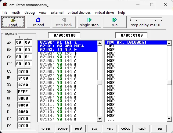
The emu8086 emulator window
MOV Examples · Step through the code
Moving a Register Value into Memory
DS:2000h is empty (00 00).
BX = 1234h; IP = 0103h.
BX is written to memory: [2000h] = 34h, [2001h] = 12h. The instruction is 4 bytes → IP = 0107h.
RET: IP = 0000h. BX is unchanged. Physical address: 07000h + 2000h = 09000h.
ORG 100h
MOV BX, 1234h     ; BB 34 12
MOV [2000h], BX   ; 89 1E 00 20
RET
MOV Examples · Step through the code
Swapping Two Registers
CX = 10 = 000Ah (numbers are decimal by default).
DX = 20 = 0014h.
XCHG swaps the two operands in one instruction: CX = 0014h, DX = 000Ah. Flags are not affected.
MOV CX, 10   ; CX = 000Ah
MOV DX, 20   ; DX = 0014h
XCHG CX, DX  ; swap
MOV Examples
XCHG Rules
- Register ↔ register:
XCHG AX, BX - Register ↔ memory:
XCHG AL, [SI] - No memory ↔ memory.
- No segment registers or immediates.
- Sizes must match; flags are unchanged.
XCHG AX, regis a one-byte instruction (XCHG AX, AX=NOP= 90h).
Without XCHG a swap would need a temporary register:
MOV AX, CX    ; AX ← CX (backup)
MOV CX, DX    ; CX ← DX
MOV DX, AX    ; DX ← old CX
That costs 3 instructions and an extra register; XCHG does it in one.
MOV Examples · Step through the code
Code Trace: Swapping with XCHG
ORG 100h
MOV SI, OFFSET num
MOV AL, 5Ah
XCHG AL, [SI]      ; AL ↔ [SI]
MOV CX, 1111h
MOV DX, 2222h
MOV AX, CX         ; backup
MOV CX, DX
MOV DX, AX         ; swapped
XCHG CX, DX        ; one instr.
RET
num DB 0A5h
SI = 0116h: the address of num; in memory num = A5h.
AL = 5Ah.
XCHG AL, [SI]: AL ↔ memory. AL = A5h, num = 5Ah. No temporary register needed.
CX = 1111h.
DX = 2222h. Now the same swap without XCHG.
MOV AX, CX: a backup of CX in AX (AX’s old value is lost).
MOV CX, DX: CX = 2222h. The old CX survives only in AX.
MOV DX, AX: DX = 1111h. The swap took 3 instructions and a register.
XCHG CX, DX: swapped back in one instruction: CX = 1111h, DX = 2222h; AX is untouched.
XCHG leaves the flags alone; there is no memory ↔ memory or segment-register exchange.
MOV Examples · Step through the code
Copying One Register into Another
SI gets a memory address (an offset): 3000h.
DI = SI = 3000h. What is copied is the address, not the data in memory.
SI and DI now point to the same cell: AL = [3000h] = 5Ah.
AL is written to [DI+1] = 3001h → 5A 5A.
MOV SI, 3000h  ; SI = address
MOV DI, SI     ; DI = SI
MOV AL, [SI]   ; DS:3000h
MOV [DI+1], AL ; DS:3001h
MOV Examples · Step through the code
Writing a Constant to a Memory Address
DS:4000h … 4003h: 00 99 00 99.
65 = 41h = 'A' is written as a single byte. Machine code C6 06 00 40 41 (5 bytes) → IP = 0105h. [4001h] is unchanged.
WORD PTR: 0041h is written → [4002h] = 41h, [4003h] = 00h (the 99h is overwritten). The instruction is 6 bytes → IP = 010Bh.
RET: IP = 0000h. A constant has no size of its own; the PTR specifier sets it.
ORG 100h
MOV BYTE PTR [4000h], 65  ; 'A'
MOV WORD PTR [4002h], 65
RET
MOV Examples · Step through the code
Copying a Register’s Low Byte into Another
AX = 1234h: AH = 12h, AL = 34h.
BX = FFFFh, to make the effect visible.
AL (the low byte of AX) is copied to BL: BL = 34h. BH is unchanged → BX = FF34h.
MOV AX, 1234h   ; AH = 12h, AL = 34h
MOV BX, 0FFFFh
MOV BL, AL      ; BL only
MOV Examples · Step through the code
Adding to a Register’s High Byte
AX = 00FFh.
AH = 00h + 01h = 01h → AX = 01FFh. Nonzero result, no carry.
AL = FFh + 1 = 00h, CF = 1, ZF = 1. The carry does not reach AH: AX = 0100h.
For comparison, AX is 01FFh again. MOV leaves the flags alone.
16-bit addition: 01FFh + 1 = 0200h; the carry passed from AL into AH, CF = 0.
MOV AX, 00FFh   ; AH = 00h, AL = FFh
ADD AH, 01h     ; AH only
ADD AL, 01h     ; AL only
MOV AX, 01FFh
ADD AX, 1       ; 16 bits
MOV Examples · Step through the code
Loading Binary, Octal and Hex Values
00000101b = 5 → AL = 05h.
0Ah = 10 → BL = 0Ah. It starts with a letter, hence the leading 0.
10o (octal) = 1×8 + 0 = 8 → CL = 08h.
AL = 5 + 10 = 15 = 0Fh. PF = 1 (0000 1111: four 1 bits).
AL = 15 − 8 = 7 = 07h. No borrow → CF = 0; PF = 0 (three 1 bits).
mov al, 00000101b ; binary
mov bl, 0ah       ; hex
mov cl, 10o       ; octal
add al, bl        ; 5 + 10 = 15
sub al, cl        ; 15 - 8 = 7
MOV Examples
Writing Numbers
| Base | Suffix | Example | Decimal value |
|---|---|---|---|
| Decimal | none or d | 25, 25d | 25 |
| Binary | b | 00011001b | 25 |
| Octal | o or q | 31o | 25 |
| Hexadecimal | h | 19h, 0FFh | 25, 255 |
| Character | ' ' | 'A' | 65 (41h) |
0Ah, 0B800h. Otherwise Ah clashes with the AH register and B800h with a label. emu8086 also accepts the 0x1000 form.MOV Examples
Common Memory-Access Mistakes
| Wrong | What happens? | Correct |
|---|---|---|
MOV SI, arr | SI gets the value of the first element, not the array’s address. | MOV SI, OFFSET arr or LEA SI, arr |
INC SI (word array) | Reads from the middle of a word: halves of two elements are combined. | ADD SI, 2 |
MOV AL, [BP] for a variable | Reads from the SS segment; in an .EXE the wrong byte comes back. | [BX], [SI] or DS:[BP] |
MOV [BX], 5 | Size unknown; the assembler reports an error or guesses. | MOV BYTE PTR [BX], 5 |
MOV AX, B800h | B800h is taken for a label name. | MOV AX, 0B800h |
| Changing DS and leaving it | Every later variable access goes to another segment. | PUSH DS … POP DS or ES |
Expecting 3412h from MOV AX, [0200h] | Little-endian forgotten: if memory holds 34 12, AX = 1234h. | Low address = low byte |
Most of these are not assembly errors: the program runs but reads from the wrong address. In emu8086, check the EA and the physical address in the memory window to find them.
Lab · 8086 instructions step by step
Lab: Memory Access
Summary
Summary
Summary
Exercises
- DS = 3000h, BX = 0010h, SI = 0005h: EA and physical address of
[BX+SI+20h]? - SS = 4000h, BP = FFFEh: EA and physical address of
[BP+4]? - Which of
[BX+BP],[DI+SI],[BX+DI+300],[DX]are valid? - If [0500h] = 78h and [0501h] = 56h, what is AX after
MOV AX,[0500h]? AL afterMOV AL,[0501h]? - Write code that puts a yellow 'X' on green at row 10, column 40 of the screen (color 2Eh).
- How would you change the previous program to write to video memory through ES without touching DS?
Answers
- EA = 0035h; physical = 30000h + 0035h = 30035h.
- EA = FFFEh + 4 = 0002h (wraps around); physical = 40002h.
- Only
[BX+DI+300]. - AX = 5678h; AL = 56h.
- Offset (10×80+40)×2 = 1680 = 690h:
MOV AX,0B800h·MOV DS,AX·MOV BX,690h·MOV WORD PTR [BX],2E58h. MOV AX,0B800h·MOV ES,AX· … ·MOV ES:[BX],CX.
Summary
References
- emu8086 documentation, 8086 assembler tutorial for beginners, part 2: memory access, MOV instruction.
- Intel, 8086/8088 User's Manual, addressing modes and instruction encoding.
- Barry B. Brey, The Intel Microprocessors, 8th ed., Pearson, Chapter 3 (Addressing Modes).
- IBM PC documentation on text-mode video memory (B800h) and the attribute byte.